CPC Definition - Subclass B23D
This place covers:
Planing, slotting, shearing, broaching, sawing, filing. scraping like operations for working metal by removing metal not otherwise provided for..
In general, although displaying sometimes a structure which can appear similar, devices which are suitable for shearing metal sheets or metal plates in the range of gauges used in industry for product manufacture are not suitable for cutting paper, plastics, fabrics etc., mainly because of blades shapes and settings. Devices for cutting paper, plastics or fabrics are mainly classified in B26D and B26F. It is observed that cutting with abrasive disks is seen as sawing, see e.g. B23D 45/00 - B23D 65/04, B27B, B28D.
This place does not cover:
Surgical saws | |
Sawing wood or similar material |
Attention is drawn to the following places, which may be of interest for search:
Punching, perforating, making articles by processing sheet metal, tubes or profiles | |
Grinding | |
Working rails in situ by planing |
In this place, the following terms or expressions are used with the meaning indicated:
Planing | Also called "shaping" this process relates to the removal of material in the form of chips by a relative movement of at least one tool with a geometrically defined cutting edge relative to a workpiece along a non-circular trajectory. Both the tool and the workpiece are non-rotating. The process is similar to turning (B23B) except that in turning either the tool is moved around the workpiece in a circular path or the workpiece is rotated. In turning the tool path is therefore circular with respect to the workpiece whereas in planing the toolpath is non-helical. |
Slotting | The production of a slot by a process similar to planing, i.e. the removal of material in the form of chips by a relative movement of at least one tool with a geometrically defined cutting edge relative to a workpiece along a non-circular trajectory. |
Shearing | To fracture material through the application of a load transverse to the material surface(s) on which the load is applied. |
Broaching | Method of machining by chip removal employing a multi-toothed cutting tool in which the functional edges of the tool teeth are so related to one another that the tip of one tooth extends further than that of an adjacent tooth from a datum line interior to the tool extending parallel to the path of relative movement between tool and work and in whose operation the teeth successively engage the work, each tooth or set of teeth removing an amount of material determined by its relationship to the adjacent tooth. |
Filing | Removal of material in the form of chips by a tool having multiple geometrically defined cutting edges arranged at similar distances from a datum line interior to the tool extending parallel to the path of relative movement between tool and work in order to produce a surface of predetermined form. |
Rasping | Filing with a course file with multiple geometrically defined raised teeth usually formed in a sheet of metal by deformation of the sheet |
Sawing | The division of a workpiece into two or more parts using a tool with a toothed, grinding or friction edge by removing material in the form of chips, dust or molten material. |
Scraping | Removal of material by a tool, generally a hand tool, comprising a geometrically defined cutting edge, used primarily to alter surface characteristics of the workpiece, rather than change the geometry. Examples include deburring by scraping (i.e. removal of sharp corners) and "roughening" of ground machine tool slideways to provide oil pockets. |
Like operations | Operations which remove metal through a geometrically defined cutting edge but for which no other provision exists within the entire classification scheme. |
This place covers:
Machines and devices for planing or slotting cutting by relative movement of the tool and workpiece in a horizontal straight line only during the machining pass . The tool or workpiece may be fed in a non-linear manner between passes to produce profiled stock.
Planing/shaping machines are generally (but not necessarily) large and typically used to produce elongate products such as rails or machine tool slideways.
rail planing machine classed in B23D 1/006
slotting machine classed in B23D 3/02
Both of the terms "planing" and "slotting" relate to the removal of material in the form of chips by a relative movement of at least one tool with a geometrically defined cutting edge and the workpiece along a non-circular trajectory. Both the tool and the workpiece are non-rotating. The process is similar to turning (B23B) except that in turning either the tool is moved around the workpiece in a circular path or the workpiece is rotated. In turning the tool path is therefore circular with respect to the workpiece whereas in planing or slotting the toolpath is non-helical.
Tools which can be used for both planing/slotting and for turning with distinctive constructional features are classed in B23B according to the functional feature. This is especially true for tool holders with replaceable indexable inserts.
This place does not cover:
Milling slots | |
Making gears or the like by planing or slotting | |
Multi stage processes involving planing/slotting and also other operations classed in B23B, B23C, B23F, making particular items. | |
Details of machine tools and accessories not related to the operation being performed including: | |
- tool changing | |
- conveying workpiece into and from machine | |
- evacuation of swarf, | |
- guarding & protective coverings | |
Adaptive control and/or computer controls for planing or slotting processes | |
- measuring or sensing | |
Planing of wood | |
Hand planes for wood |
Attention is drawn to the following places, which may be of interest for search:
Details of turning tools which may also be usable as planing or slotting tools | |
Details of turning tool holders which may also be usable as planing or slotting tool holders | |
Machines for milling of window frames which may include slotting tools | |
Planing or slotting of gear teeth | |
Planing or slotting tools for making gear teeth | |
Constructional features of machine tools in general | |
Features of copying devices |
The use of planing and slotting machines in metal working is not as widespread as it once was as a result of developments in milling machines and computer controls for milling machines. The field is therefore relatively slow-moving and classification in these groups is simply according to a literal interpretation of the group and subgroup headings. The feed movement of B23D 1/28 refers to the relative feed movement of the tool and workpiece between the linear cutting passes.
In patent documents, the following words/expressions are often used with the meaning indicated:
"planing" | "shaping" |
This place covers:
Planing or slotting machines cutting by relative movement of the tool and workpiece in a vertical or inclined straight line. The tool or workpiece may be fed in a non-linear manner between passes to produce profiled stock.
This place covers:
Planing or slotting machines cutting otherwise than by relative movement of the tool and workpiece in a straight line, i.e. in which the actual cutting stroke is not linear, so that non-prismatic surfaces can be produced..
This place covers:
Planing or slotting machines characterised only by constructional features of particular parts. If characterising features relate to the pillars or to the cross beam, document should be classed in B23D 7/04, rather than in B23D 7/02, as these terms are more specific than the term "frame" of B23D 7/02.
This place covers:
Hand-operated planing devices; Portable planing apparatus
This place covers:
Planing or slotting devices able to be attached to a machine tool that is not primarily designed for planing or slotting, whether or not replacing an operative portion of the machine tool
This place covers:
Tools or tool holders specially designed for planing or slotting machines
This place covers:
Metal sheets, metal plates and metal bars or rods shearing devices comprising at least one blade which translates or roto-translates, in the latter case the blade being articulated about at least two pivoting links, the cooperating cutting edges of the shearing devices being offset or abutting.
Abutting means that the cutting edges pinch the material betweeen them and the blades do not essentially cross.
This place covers:
Metal sheets, metal plates and metal bars or rods shearing devices comprising at least one elongated, possibly curved blade which rotates (completely or partially), or roto-translates, the blade being articulated about a single pivoting link, the cooperating cutting edges of the shearing devices being offset or abutting.
This place does not cover:
Disc blades |
Abutting means that the cutting edges pinch the material between them and the blades do not essentially cross.
This place covers:
Shearing machines or shearing devices cutting by rotary discs, the cooperating cutting edges of the shearing devices being offset or abutting.
Abutting means that the cutting edges pinch the material between them and the blades do not essentially cross.
This place covers:
Devices for shearing (the cooperating cutting edges of the shearing devices being offset or abutting) or cutting tubes. The term tube is to be intended as a profile showing a continuous, convex, closed section.
This place does not cover:
Cutting profiles | |
Sawing devices with circular blades for cutting tubes | |
Cutting by turning | |
Cutting by milling |
Abutting means that the cutting edges pinch the material between them and the blades do not essentially cross.
This place covers:
Devices for shearing (the cooperating cutting edges of the shearing devices being offset or abutting) or cutting metal profiles showing a discontinuous, concave or open section, window coverings, window or door profiles.
This place does not cover:
Cutting tubes | |
Turning | |
Milling |
Abutting means that the cutting edges pinch the material between them and the blades do not essentially cross.
This place covers:
Machines or arrangements for shearing stock while the latter is travelling otherwise than in the direction of the cut, the cooperating cutting edges of the shearing devices being offset or abutting (i.e. flying shears).
Abutting means that the cutting edges pinch the material between them and the blades do not essentially cross.
This place covers:
Machines or devices comprising at least one punch like tool and adapted to produce a line of cut which is the result of a sequence of overlapping punching operations.
This place covers:
Devices in which the cooperating cutting edges of the shearing devices are offset or abutting.
This place does not cover:
Hand operated shearing devices comprising abutting cutting edges |
Abutting means that the cutting edges pinch the material between them and the blades do not essentially cross.
This place covers:
In addition to combinations of similar or different shearing machines as defined in the preceding main groups, breaking machines (e.g. for rails, connecting rods, rings), demolition shears, devices for trimming deep drawn products outside the press.
Attention is drawn to the following places, which may be of interest for search:
Disintegrating by knives | |
Trimming combined with deep-drawing presses |
This place covers:
Feeding, holding, positioning or guiding stock directly into the operating area of the shearing machines or devices, devices for indicating the position of the cut.
Attention is drawn to the following places, which may be of interest for search:
Indicating the position of the cut |
The accessories are meant to be part of the shear, a feeder of a general purpose should be classified in B21D 43/00 (see title)
This place covers:
Shapes and sections of the cutting members, means for mounting and adjusting the position of cutting members
Shapes can be any shape, sections are profiles of cutting members as viewed across their sections
This place covers:
Control means for coordinating the action between feeding means and shearing means
Attention is drawn to the following places, which may be of interest for search:
Control means for cutting non metallic workpieces |
This place covers:
Broaching machines or devices. Broaching is similar to shaping/planing (B23D 1/00-B23D 13/00) except that a tool with multiple teeth is employed. The difference in height between successive teeth on a broaching tool determines the feed, and hence the chip thickness, whereas in shaping or planing the feed is determined by a relative movement between tool and workpiece between each pass.
Broaching of cylindrical workpieces e.g. crankshafts B23D 37/005
Horizontal broaching machine B23D 37/04
Vertical Broaching machine for inner surface B23D 37/10
Broaching machine with tools on chain B23D 37/18
Broaching is similar to shaping/planing (B23D 1/00-B23D 13/00) except that a tool with multiple teeth is employed. The difference in height between successive teeth on a broaching tool determines the feed, and hence the chip thickness, whereas in shaping or planing the feed is determined by a relative movement between tool and workpiece between each pass.
This place does not cover:
Making gears or the like by broaching | |
Multi stage processes involving broaching and also other operations classed in B23B, B23C, B23F, making particular items. | |
Details of machine tools and accessories not related to the operation being performed including: | |
- tool changing | |
- conveying workpiece into and from machine | |
- evacuation of swarf, | |
- guarding & protective coverings | |
Adaptive control and/or computer controls for broaching processes | |
- measuring or sensing |
Attention is drawn to the following places, which may be of interest for search:
Turning of crankshafts or camshafts | |
Fixation of cutting inserts in metal-removing tools | |
Milling of crankshafts | |
Milling of camshafts | |
Construction of milling tools | |
Broaching of gears | |
Broach-milling tools for making gears | |
Broaching tools for making gears | |
Manufacture of crankshafts or camshafts | |
Constructional features of machine tools in general |
B23D 37/005 for rotary broaching takes precedence over all other subgroups
Classification in this group is simply according to a literal interpretation of the group and subgroup headings, taking into account the notes concerning precedence and the references contained within the subgroups. The term "horizontally arranged" of B23D 37/02 should be understood a meaning arranged so the teeth or the broach are arranged in a generally horizontal plane and the tool moves horizontally with respect to the workpiece. Similarly the teeth of the broaching tools of B23D 37/08 are arranged in a generally vertical plane and the tool describes a generally vertical motion with respect to the workpiece.
This place covers:
Accessories for broaching machines or broaching devices. Broaching is similar to shaping/planing (B23D 1/00-B23D 13/00) except that a tool with multiple teeth is employed. The difference in height between successive teeth on a broaching tool determines the feed, and hence the chip thickness, whereas in shaping or planing the feed is determined by a relative movement between tool and workpiece between each pass.
Classification in this group is simply according to a literal interpretation of the group and subgroup headings, taking into account the notes concerning precedence and the references contained within the subgroups.
This place covers:
Broaching machines or broaching devices characterised only by constructional features of particular parts. Broaching is similar to shaping/planing (B23D 1/00-B23D 13/00) except that a tool with multiple teeth is employed. The difference in height between successive teeth on a broaching tool determines the feed, and hence the chip thickness, whereas in shaping or planing the feed is determined by a relative movement between tool and workpiece between each pass.
Classification in this group is simply according to a literal interpretation of the group and subgroup headings, taking into account the notes concerning precedence and the references contained within the subgroups.
This place covers:
Broaching tools. Broaching is similar to shaping/planing (B23D 1/00-B23D 13/00) except that a tool with multiple teeth is employed. The difference in height between successive teeth on a broaching tool determines the feed, and hence the chip thickness, whereas in shaping or planing the feed is determined by a relative movement between tool and workpiece between each pass. Broaching tools are multi-toothed cutting tools in which the geometrically defined functional edges of the tool teeth are so related to one another that the tip of one tooth (or set of teeth) extends further than that of an adjacent tooth (or set of teeth) from a datum line interior to the tool extending parallel to the path of relative movement between the tool and the work and in whose operation the teeth successively engage the work, each tooth or set of teeth removing an amount of material determined by its relationship to the adjacent tooth (or set of teeth). In the case of rotary broaches no relative movement is necessary between the axis of the tool and the work in order to effect cutting.
linear broach B23D 43/02
Rotational broach B23D 43/06
Classification in this group is simply according to a literal interpretation of the group and subgroup headings, taking into account the notes concerning precedence and the references contained within the subgroups.
This place covers:
- Machines or devices for sawing in general or sawing metal (B23D 45/00, B23D 49/00, B23D 53/00, B23D 57/00)
- Accessories specially designed for sawing machines or sawing devices (B23D 59/00)
- Tools for sawing machines or sawing devices, clamping devices for these tools, saw blades (B23D 61/00)
- Dressing the tools of sawing machines or sawing devices (B23D 63/00)
- Making tools for sawing machines or sawing devices (B23D 65/00)
B23D is the main entry for sawing. Other large areas covering sawing are B27B (sawing wood or similar material) and B28D 1/02 (sawing stone). Precedence is given to B23D. Features not restricted to a particular type of saw are classified in B23D. However, such features are classified in B27B if a more specific entry exists in B27B, for example:
- B27B 5/30: mounting/securing devices for circular saw blades or spindles
- B27B 5/38: braking devices for the circular saw blade or the spindle
- B27B 17/00: details of chain saws, equipment for chain saws
- B27B 27/00: guide fences or stops
- B27B 33/14: saw chains
This place does not cover:
Shearing machines with rotary discs | |
Control of machines with circular saw blades for sawing stock while the latter is travelling otherwise than in the direction of the cut | |
Constructional features of particular parts per se | |
Grinders for cutting-off | |
Details or components, e.g. casings, bodies, of portable power-driven saws not particularly related to the operation performed | |
Safety guards or devices specially designed for saws |
Examples of places where the subject matter of this place is covered when specially adapted, used for a particular purpose, or incorporated in a larger system:
Sawing wood or similar material | |
Sawing stone or stone-like materials | |
Accessories specially adapted for use with machines for sawing of gems, jewels, crystals | |
Sawing gems, jewels, crystals with discs or wheels | |
Sawing gems, jewels, crystals with blades or wires | |
Accessories specially adapted for use with machines or devices for sawing stone |
Attention is drawn to the following places, which may be of interest for search:
Saws specially adapted for pruning or debranching | |
Sawing apparatus specially adapted for felling trees | |
Meat or bone saws | |
Surgical saws | |
Saws for dentistry | |
Grinders for cutting-off | |
Auxiliary devices facilitating proper operation of wood saws |
In this place, the following terms or expressions are used with the meaning indicated:
Feeding work | moving a workpiece into engagement with a saw blade while sawing |
Conveying or transporting work | moving a workpiece before, after or between sawing operations |
Discharging work | moving a workpiece away from a saw blade after sawing |
This place covers:
Features of saws which are specific for a particular application, for example, devices for sawing venetian window blinds, railroad rails, pallets.
Attention is drawn to the following places, which may be of interest for search:
Machines for disassembling pallets | |
Sectioning or slitting rails, e.g. by sawing, shearing, flame-cutting | |
Devices or accessories for making or mounting lamellar blinds or parts thereof |
Attention is drawn to the following places, which may be of interest for search:
Sectioning or slitting rails, e.g. by sawing, shearing, flame-cutting |
This place covers:
(EP 1 772 221 A1)
This place does not cover:
Details or components, e.g. casings, bodies, of portable power-driven saws not particularly related to the operation performed |
Attention is drawn to the following places, which may be of interest for search:
Circular saw blades, clamping devices therefor | |
Constructional features of particular parts per se | |
Details; Component parts; Accessories for circular wood saws | |
Mounting or securing circular saw blades or saw spindles | |
Devices for braking the circular saw blade or the saw spindle; Devices for damping vibrations of the circular saw blade, e.g. silencing | |
Arrangements for adjusting the cutting depth or the amount of tilting of portable power-driven circular saws for manual operation | |
Guiding equipment for portable power-driven circular saws for manual operation | |
Guide fences |
Reference B23Q is non-limiting in the main group B23D 47/00. CPC will be updated/corrected once this inconsistency is resolved in IPC.
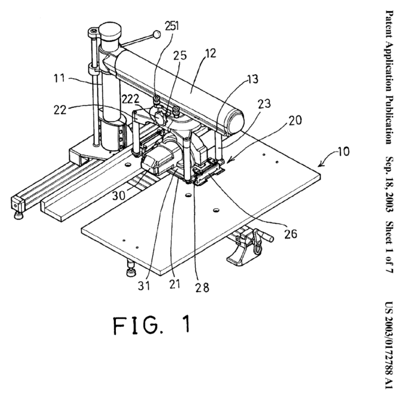
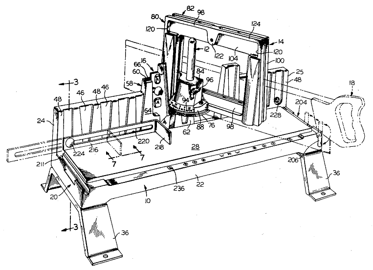
This place covers:
A mechanism for locking or otherwise holding the blade at an angle when adjusting about an axis parallel to the work support surface. Generic blade pivoting need not be placed here.
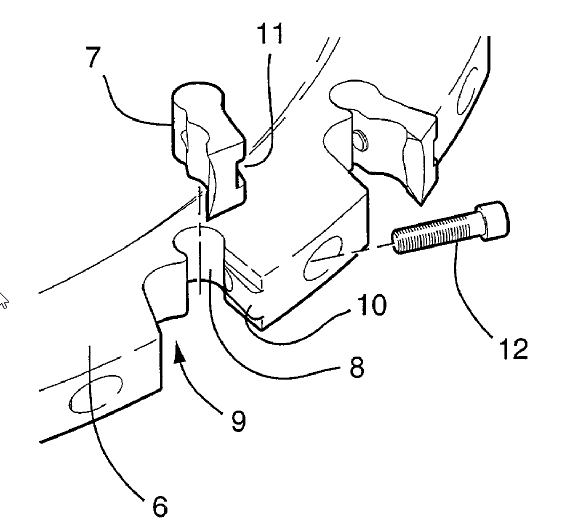
Illustrative example of subject matter classified in this place:
Note, in the figure below, bevel adjustment mechanism 40 for adjusting rotational angle about axis 48 is illustrated as including a locking knob.
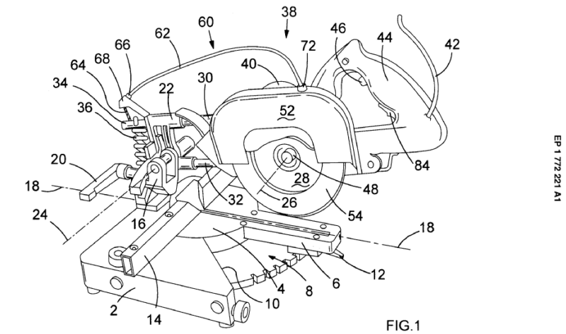
This place covers:
A mechanism for locking or otherwise holding the blade at an angle when adjusting about an axis perpendicular to the work support surface. Generic blade pivoting need not be placed here.
Illustrative example of subject matter classified in this place:
Note, in the figure below, locking mechanism includes lever 134 which is actuated to disengage a detent from one of the recesses 42.
Attention is drawn to the following places, which may be of interest for search:
Hacksaws with bows adjustable in length or height |
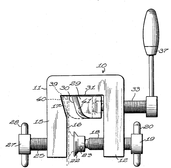
This place covers:
Illustrative example of subject matter classified in this place:
Note, in the figure below, a reciprocating blade combined with a rotating blade.
This place covers:
Illustrative examples of subject matter classified in this place:
Note, in Fig. 1 below, a reciprocating saw that has been converted to a sander.
1.
Note, in Fig. 2 below, a reciprocating saw that has been converted to a rotary saw.
2.
This place covers:
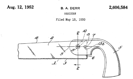
(US 2 606 584)
This place covers:
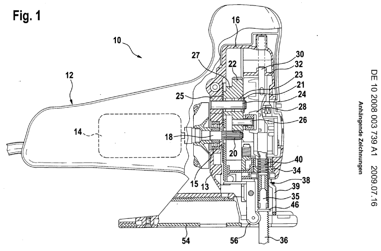
(DE 10 2008 003 739 A1)
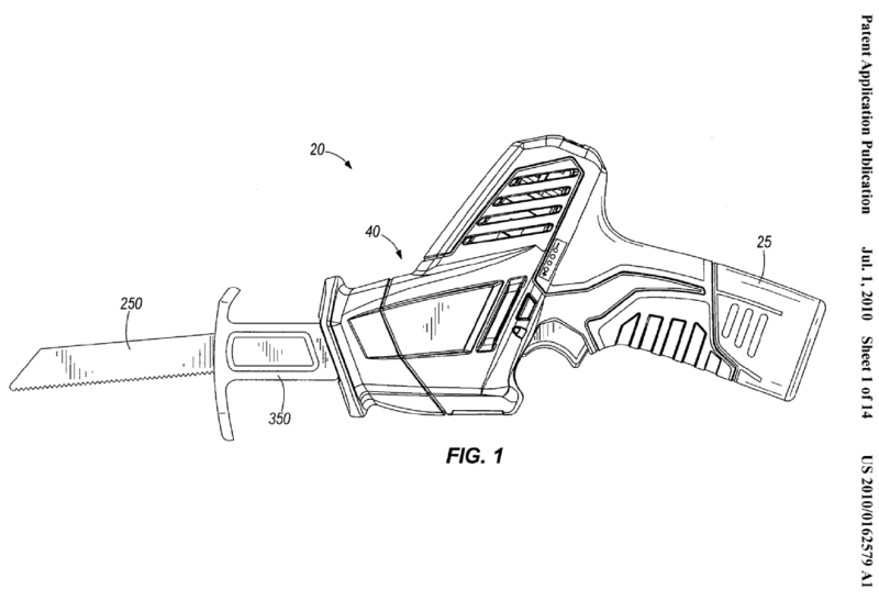
(US 2010/0162579 A1)
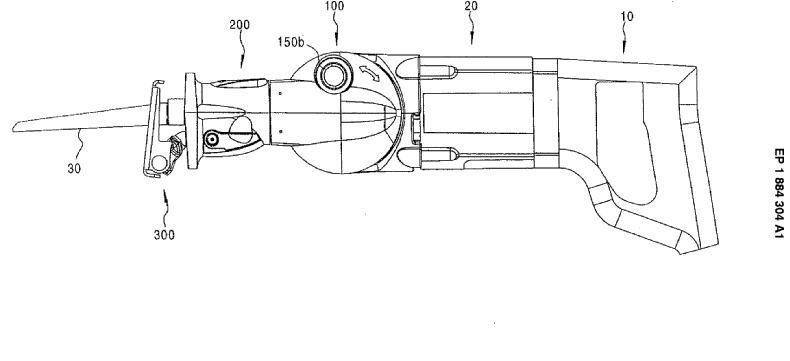
(EP 1 884 304 A1)
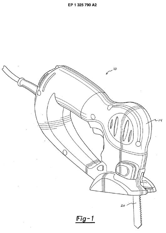
(EP 1 325 790 A2)
This place covers:
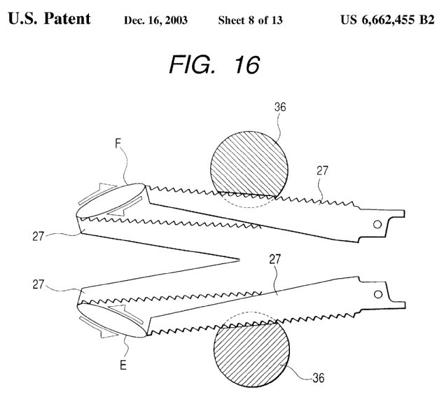
US 6 662 455 B2
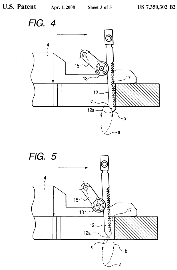
US 7 350 302 B2
This place covers:
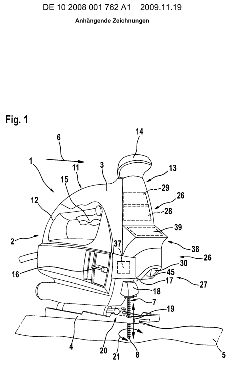
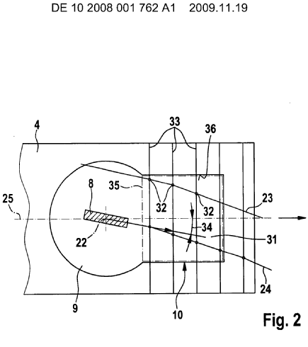
the saw blade being rotatable around its longitudinal axis during sawing for sawing along a curved path (DE 10 2008 001 762 A1)
the saw being angularly adjustable relative to its foot plate
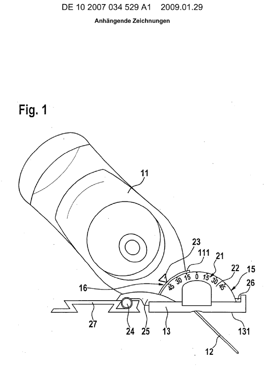
(DE 10 2007 034 529 A1)
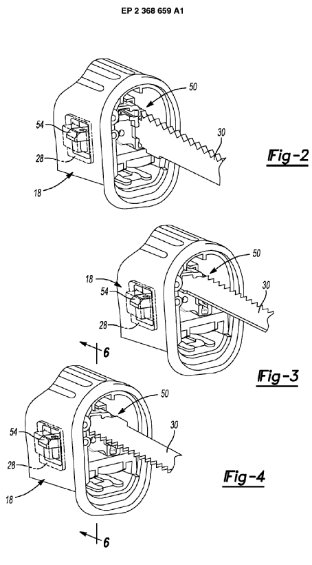
the saw blade being mountable in different planes (EP 2 368 659 A1)
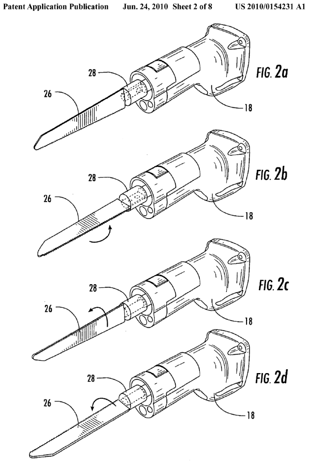
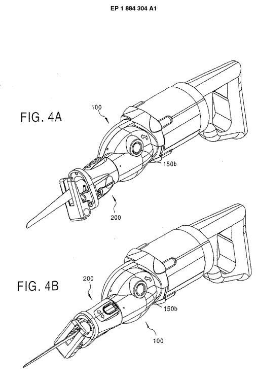
the saw blade being adjustable in different planes (US 2010/0154231 A1 and EP 1 884 304 A1)
This place covers:
Illustrative example of subject matter classified in this place:
Note, in the figure below, the pivoting of the reciprocating saw carriage.
This place does not cover:
Straight saw blades | |
Constructional features of particular parts per se | |
Details or components, e.g. casings, bodies, of portable power-driven saws not particularly related to the operation performed | |
Guide fences |
Attention is drawn to the following places, which may be of interest for search:
Arrangements for stretching the saw blade of hand saws without power drive for sawing wood |
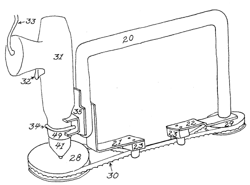
This place covers:
Illustrative example of subject matter classified in this place:
Note, in the figure below, how a guide is contacting both sides of the reciprocating blade.
This place covers:
Adjustment providing a wider or narrower space for the blade, or for part of the tool that moves with the blade, or for the workpiece.
This place covers:
Illustrative example of subject matter classified in this place:
Note, in the figure below, the horizontal pivot axis.
This place covers:
Illustrative example of subject matter classified in this place:
Note, in the figure below, the vertical pivot axis.
This place covers:
Devices provided with a counterbalancing means to negate or neutralize the kinetic effect of the tool.
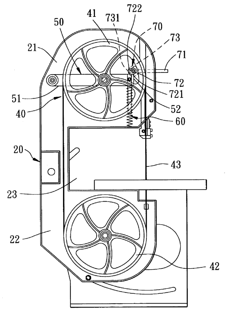
This place covers:
Devices provided with dampers, springs or similar mechanisms to dissipate, or render less harmful, the vibrations or "jars" caused by the to-and-fro movements of the tool. These mechanisms could be in the drive train, the housing, the handle or elsewhere.
This place covers:
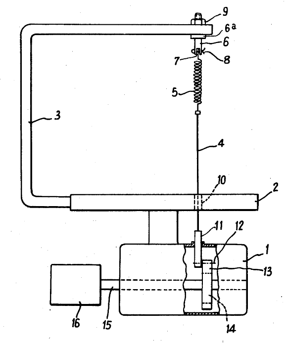
Devices having means which capture energy to move or assist in moving the tool in the opposite direction of the tool movement.
Illustrative example of subject matter classified in this place:
The energy storing mechanism is shown as a spring (5) in the figure below.
This place does not cover:
Band or strap sawing machines specially designed for length cutting of trunks with a plurality of band saw blades |
This place covers:
Illustrative example of subject matter classified in this place:
Note, in the figure below, how one blade section abuts another blade section, but is running in the opposite direction.
This place covers:
Illustrative example of subject matter classified in this place:
Note, in the figure below, how the two blades (B) can have their spacing adjusted left and right.
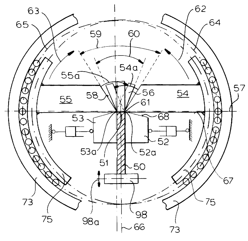
This place covers:
Devices wherein the space varying means is a member pivoted about a fulcrum.
Illustrative examples of subject matter classified in this place:
Note the levers (63,65).
1.
Note the scissoring levers (19).
2.
This place covers:
Devices wherein the space varying means is a member having a helical rib thereon that is mated with a second member so that relative rotation between the members varies the spacing between cutting spans.
This place covers:
Illustrative example of subject matter classified in this place:
This place covers:
Devices in which the distance between the plane of the cutting span and the plane of the work support surface is changed such that the distance between the cutting span and the work support surface is varied while maintaining the orientation between the cutting span and the support surface.
Illustrative example of subject matter classified in this place:
Note, in the figure below, the positional change shown in phantom.
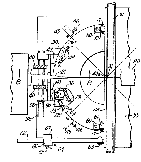
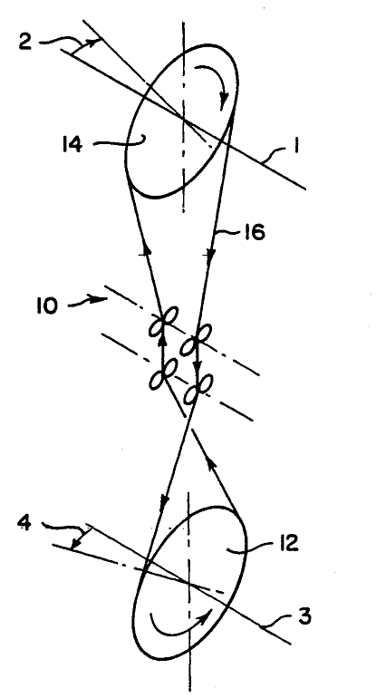
This place covers:
Angularly adjustable band saw blades which in addition to pivoting or shifting during sawing, the band saw can also pivot to adjust the angle of the cut.
Illustrative example of subject matter classified in this place:
Note, in the below figure, how the blade (21) can change angles relative to workpiece (W).
Attention is drawn to the following places, which may be of interest for search:
Constructional features of a shiftable or swinging work-table | |
Strap saw blades, for example with incorporated tensioning devices | |
Constructional features of particular parts per se | |
Guide fences |
Reference B23Q is non-limiting in the main group B23D 55/00. CPC will be updated/corrected once this inconsistency is resolved in IPC.
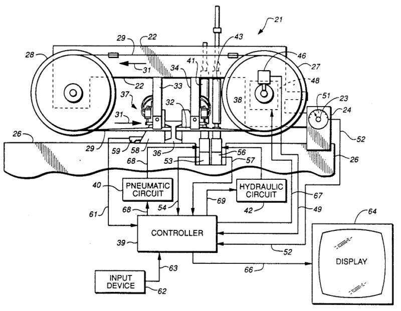
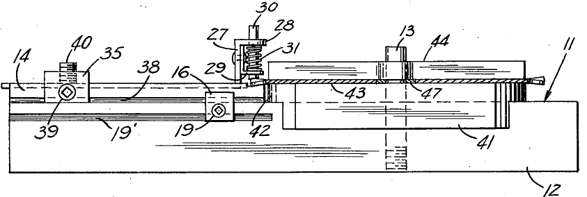
This place covers:
Illustrative example of subject matter classified in this place:
Note, in the figure below, where a hydraulic and pneumatic cylinder control the advancement of the blade through the workpiece.
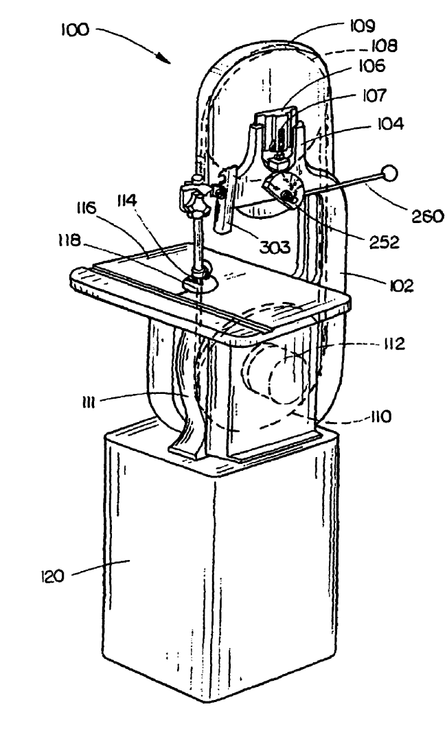
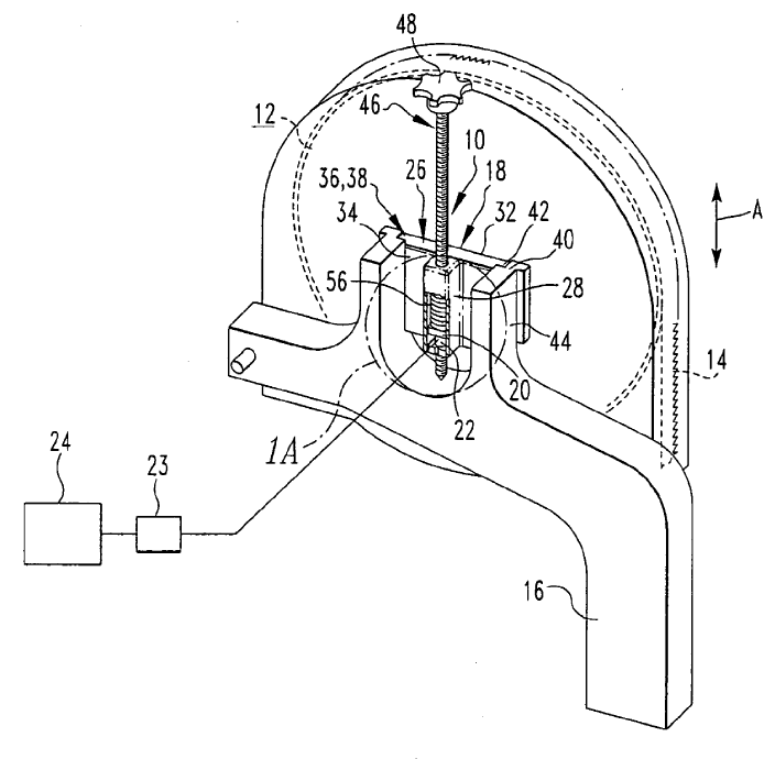
This place covers:
Illustrative examples of subject matter classified in this place:
Note, in figure 1 below, a cam (252) is used to change the distance between one pulley and the other.
1.
Note, in figure 2 below, a screw adjustment (10) for adjusting the distance between the pulleys.
2.
This place covers:
Yieldable biasing means, e.g. hydraulics, counterweights, springs.
Illustrative example of subject matter classified in this place:
Note the spring (60) in the figure below.
This place covers:
Illustrative example of subject matter classified in this place:
Note the angle changes (2,4) in the figure below.
This place covers:
For example: wire saws, chain saws, saws for sawing under water or at places accessible with difficulty.
This place does not cover:
Saw wires | |
Constructional features of particular parts per se | |
Details of chain saws, equipment for chain saws | |
Saw chains |
Attention is drawn to the following places, which may be of interest for search:
Grinders for cutting-off using a cutting wire |
This place does not cover:
Devices for removing chips for machine tools in general | |
Lubricating or cooling machine tools in general | |
Mounting for swivelling or tilting a circular saw blade | |
Arrangements for adjusting the cutting depth or the amount of tilting of portable power-driven circular saws for manual operation | |
Guide fences | |
Measuring in general | |
Controlling in general |
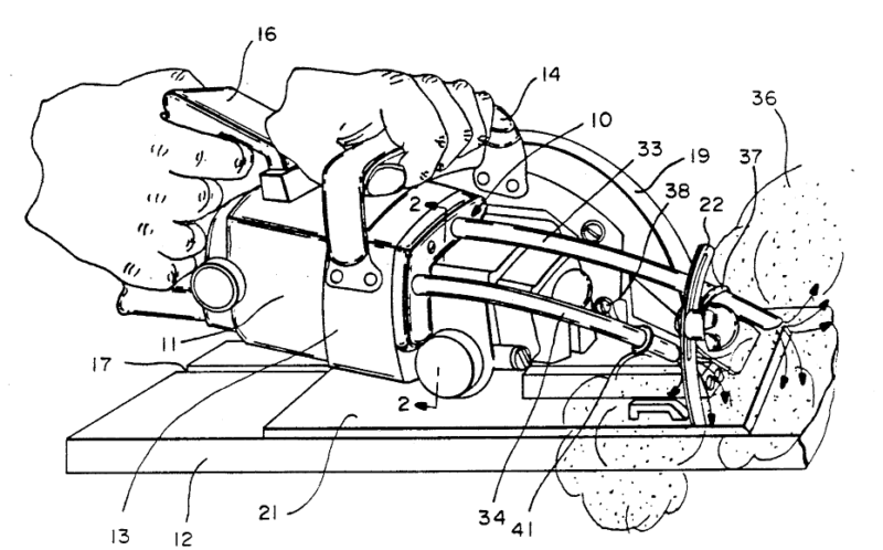
This place covers:
Illustrative example of subject matter classified in this place:
Note, in the figure below, the tubes (33,34) that blow air against the sawdust.
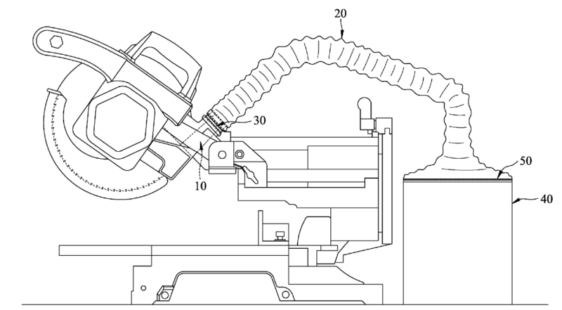
This place covers:
Illustrative example of subject matter classified in this place:
Note, in the figure below, the tube (20) that sucks the sawdust away from the saw.
This place does not cover:
Devices for mounting straight saw blades or other tools | |
Tools for trepanning | |
Cut-off wheels of bonded abrasive or with inserted abrasive blocks | |
Mounting or securing circular saw blades or saw spindles | |
Saw chains |
Attention is drawn to the following places, which may be of interest for search:
Grinders for cutting-off using a cutting wire |
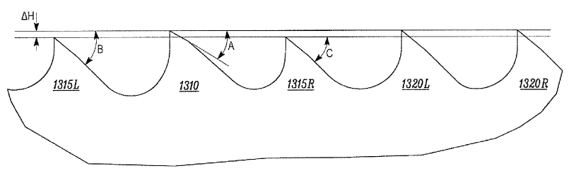
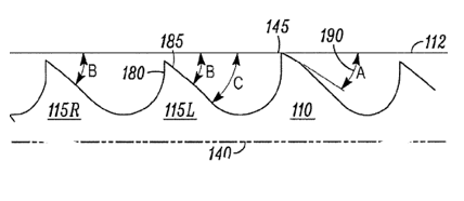
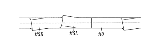
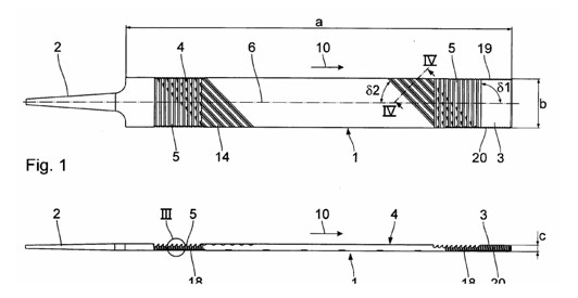
This place covers:
Saw blades where the distance between teeth varies in the direction of travel.
Illustrative example of subject matter classified in this place:
This place covers:
Saw blades where the distance from a tooth tip to the center of rotation varies from one tooth to another tooth.
Illustrative example of subject matter classified in this place:
This place covers:
Saw blades having a depth limiter that prevents the cutting tooth from penetrating further into the workpiece.
Illustrative example of subject matter classified in this place:
Note, in the figure below, element (24) acts as a depth limiter.
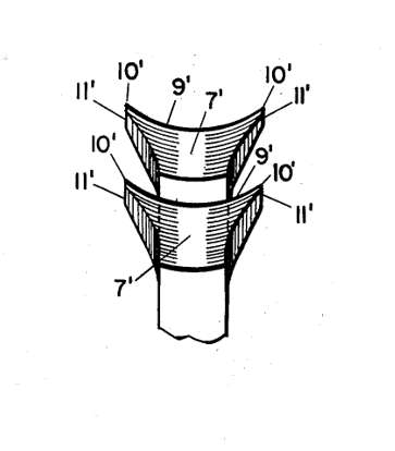
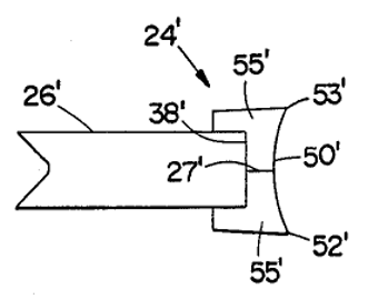
This place covers:
Illustrative examples of subject matter classified in this place:
Note, in the figures below (Fig. 1a and 1b), the cutting edge (9' in Fig. 1b) is curved in a direction transverse to the plane of the blade.
1a.
1b.
Note, in Fig. 2 below, the cutting edge (50') is curved in a direction transverse to the plane of the blade.
2.
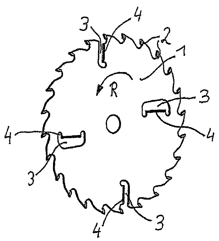
This place covers:
Illustrative example of subject matter classified in this place:
Note elements (4) in the figure below.
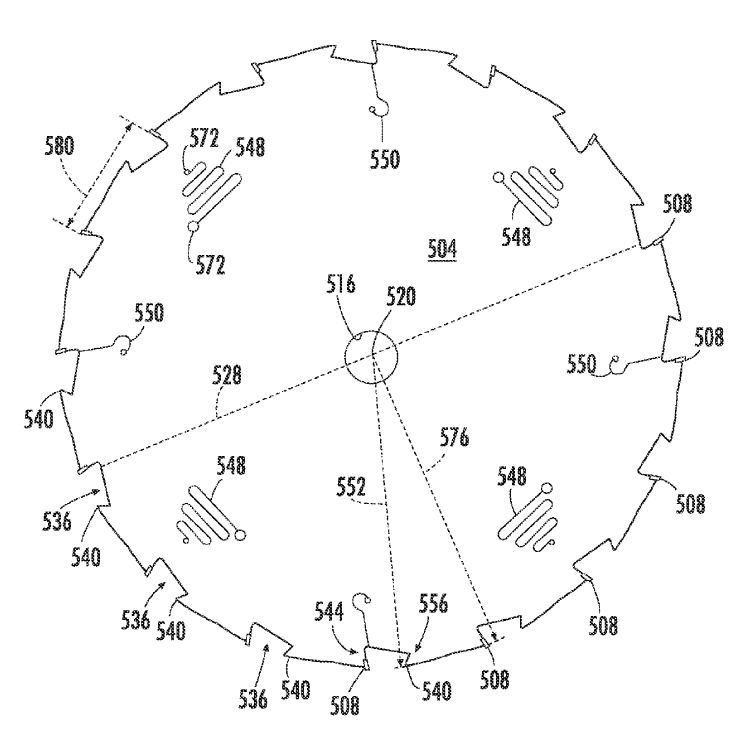
This place covers:
Slots on the saw blade body for reducing tension or vibration. The slots could extend to the periphery.
Illustrative example of subject matter classified in this place:
Note slots (548, 550) in the figure below.
This place covers:
Saw blades having at least one independent connecting element, e.g. a bolt, that is separable from the saw blade body for connecting a tooth.
Illustrative examples of subject matter classified in this place:
Note, in Fig .1 below, connecting element 12, but could be any element so long as it is separable from the saw blade body
1.
Note, in Fig. 2 below, connecting element 4.
2.
This place covers:
Circular saw blades with exchangeable inserted saw teeth connected by a flexible portion that could be part of the tooth, of the blade body or of a connecting element.
Illustrative example of subject matter classified in this place:
Note flexible element 3 in the figure below.
This place covers:
Saw blades where the distance between teeth varies in the direction of travel.
Illustrative example of subject matter classified in this place:
This place covers:
Saw blades where the height of one tooth varies from the height of another tooth.
Illustrative example of subject matter classified in this place:
This place covers:
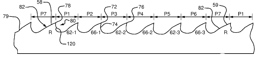
Saw blades having repeating patterns of groups of teeth, where each group of teeth includes at least three teeth. Within a group of three or more teeth, there is a variance among the teeth, and the variance can include tooth width, angle, height, set or other change that affects the size or position of a cutting edge of the tooth.
Illustrative example of subject matter classified in this place:
In Fig. 1a below, note the variance between the 3 tooth angles shown in side view
1a.
In Fig. 1b below, shown in top view of the detail of Fig. 1a, is a simple example of a repeating group of teeth with left-set, right-set, no-set.
1b.
This place covers:
Reciprocating blades having plurality of tooth sections that are large enough such that only one section engages the workpiece at a time.
Illustrative example of subject matter classified in this place:
Note, in the figure below, the different tooth sizes in each section in the blade.
This place covers:
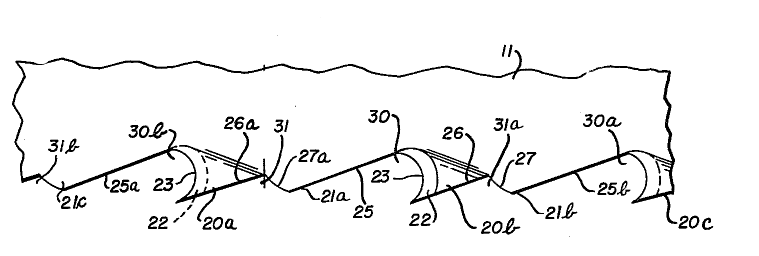
Linear saw blades having a depth limiter that prevents the cutting tooth from penetrating further into the workpiece.
Illustrative example of subject matter classified in this place:
Note elements 21a, 21b, 21c shown in the figure below that act as depth limiters.
This place covers:
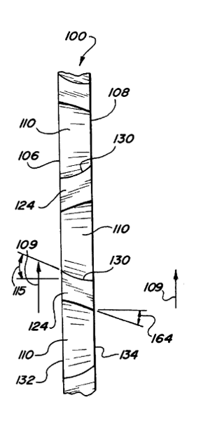
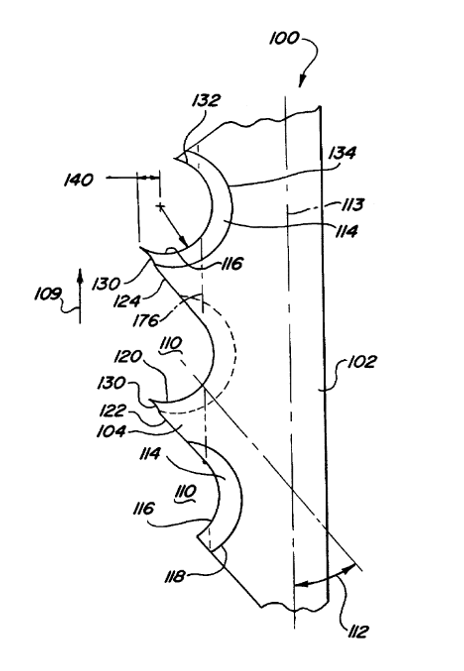
Illustrative example of subject matter classified in this place:
Note, in the figures (1a - cross section view and 1b side view) shown below, a transversely curved cutting edge (130).
1a.
1b.
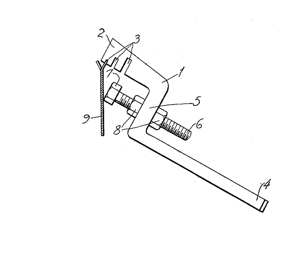
This place covers:
Illustrative example of subject matter classified in this place:
Note, in the figure below, elements 4.
This place covers:
Slots on the saw blade for reducing tension or vibration. The slots can extend to the blade edge.
Illustrative example of subject matter classified in this place:
Note, in the figure below, slots 6.
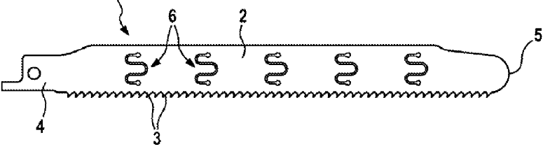
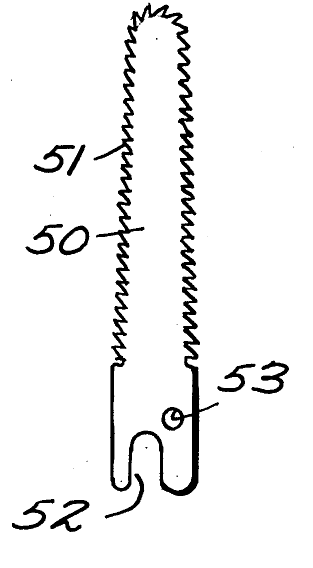
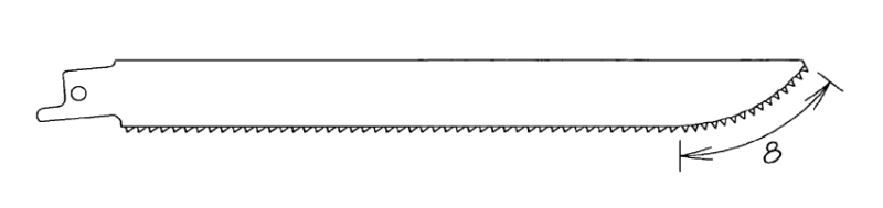
This place covers:
Saw blades having noses with teeth on them that enables a user to start making a cut in the middle of a planar workpiece.
Illustrative examples of subject matter classified in this place:
1.
2.
This place covers:
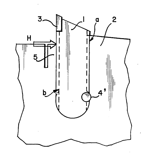
Saw blades having exchangeable saw teeth, where the teeth are connected to the saw blade body with at least one independent connecting element. The connecting element is most often a bolt, but can be any element that is separable from the saw blade body.
Illustrative examples of subject matter classified in this place:
Note, in Fig. 1 below, connecting element 28 in Fig. 1 figure below.
1.
Note, in Fig. 2 below, connecting element 4'.
2.
This place covers:
Saw blades having exchangeable saw teeth, where the teeth are connected to the saw blade body by a flexible portion, where the flexible portion can be part of the tooth, part of the blade body, or part of a connecting element.
Illustrative example of subject matter classified in this place:
Note, in the figure below, element 3 is flexible.
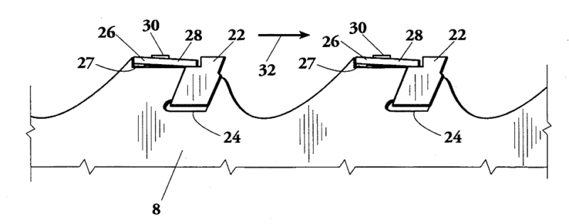
This place covers:
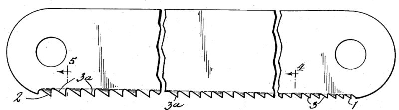
Mechanisms for feeding the saw to the devices which operate upon the saw handle or teeth, which comprise a reciprocating pawl or other means for engaging successive teeth of the saw to feed the saw forward.
Illustrative example of subject matter classified in this place:
Note, in the figure below, pawl 30 that engages teeth successively.

This place covers:
Machines in which the tooth-setting devices are forced into engagement with the teeth by means of a screw.
Illustrative example of subject matter classified in this place:
Note, in the figure below, screw 33.
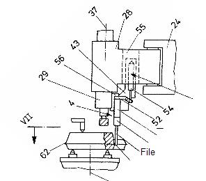
This place covers:
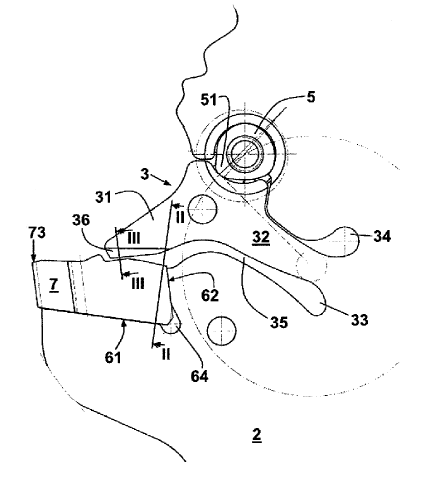
Machines in which the tooth-setting devices are forced into engagement with the teeth by a pivoting motion.
Illustrative example of subject matter classified in this place:
Note, in the figure below, elements 54 and 55, which pivot along arrows 62,63.
This place covers:
Machines in which the tooth-setting devices are linearly sliding into engagement with the teeth.
Illustrative example of subject matter classified in this place:
Note, in the figure below, element 30 which slides vertically.
This place covers:
Machines and implements having means for embracing the tooth, the lateral (or oscillating) movement of the device serving to bend the tooth to the proper set without the cooperation of an anvil. Machines and implements covered by this classification place are mainly manual devices, but some powered devices are covered also by this group.
Illustrative example of subject matter classified in this place:
Note, in the figure below, the tooth is embraced by the slot 3 and then bent, without the use of any anvil
This place covers:
Furbishing apparatus for making the teeth a desired common height.
The jointing tool could also be things other than an abrading tool, such as a deforming tool.
Illustrative example of subject matter classified in this place:
Note, in the figure below, an abrading tool (8) can be used to set the tooth height.
Attention is drawn to the following places, which may be of interest for search:
Heat treatment for saw blades |
This place covers:
Tooth inserting tools especially adapted for inserting saw teeth into a saw blade or extracting saw teeth from the saw blade.
Illustrative examples of subject matter classified in this place:
Note, as shown in Fig. 1 below, the tooth inserting tool could be a simple hand tool.
1.
Note, as shown in Fig. 2 below, the tooth inserting tool could be a more complicated machine.
2.
This place covers:
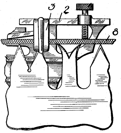
Filing or rasping machines or devices; Filing entails the removal of material in the form of chips by a tool having multiple geometrically defined cutting edges arranged at similar distances from a datum line interior to the tool extending parallel to the path of relative movement between tool and work in order to produce a surface of predetermined form. Rasping is a type of filing using a course file with multiple geometrically defined raised teeth usually formed in a sheet of metal by deformation of the sheet.
Illustrative example(s) of the subject matter classified in this group:
Filing machine with reciprocating tool B23D 67/02 or B23D 67/04

Rasping machine with rotary tool for rubber like materials (tyres)
B23D 67/06, B23D 67/10 (and additionally B23D 71/025)
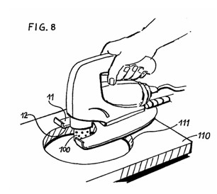
Hand held rasping machine B23D 67/12
Filing or rasping is similar in nature to grinding, which is classified in B24B and B24D. The principal difference between grinding and rasping or filing is that in grinding material is removed by a tool having cutting edges of undefined angles. Grinding tools usually consist of abrasive particles embedded in a fixing medium. In filing or rasping the approach and rake angles of the cutting edges are usually known and determined by the configuration of the tool. Files generally have rows or fine teeth arranged in a pattern and are used for relatively precise work. Rasps are in general designed for coarser (rougher) work and may (but may not) have randomly arranged cutting edges.
This place does not cover:
Sharpening saw teeth by filing | |
Securing arrangements for files or rasps | |
Sharpening files by etching | |
Methods or machines for the manufacture of files or rasps that use non-mechanical methods | subclass according to non-mechanical method |
Examples of places where the subject matter of this place is covered when specially adapted, used for a particular purpose, or incorporated in a larger system:
Sharpening saw teeth by filing |
Attention is drawn to the following places, which may be of interest for search:
Farriers' tools including files for horses' hooves | |
Personal grooming including nail files | |
Bone rasps and other tools for surgery | |
Veterinary instruments for animals' teeth including files | |
Constructional features of machine tools in general | |
Grinding machines and methods | |
Abrasive Blasting including sandblasting | |
Grinding tools | |
Chisels for metal | |
Handles for hand implements | |
Rasps for wood | |
Recovery of plastics from other materials including rasping of tyres | |
Sharpening files by etching |
Classification in group B23D 67/00 is simply according to a literal interpretation of the group and subgroup headings, taking into account the notes concerning precedence and the references contained within the subgroups.
This place covers:
Filing or rasping machines or devices. characterised only by constructional features of particular parts, e.g. guiding arrangements, drives
Accessories for filing or rasping.
This place covers:
Filing or rasping tools and securing arrangements for filing and rasping tools. Filing tools generally have multiple geometrically defined cutting edges arranged at similar distances from a datum line interior to the tool extending parallel to the path of relative movement between tool and work in order to produce a surface of predetermined form by chip removal. A rasp is a type of course file with multiple geometrically defined raised teeth usually formed in a sheet of metal by deformation of the sheet.
Rotary filling tool B23D 71/005
Rasping machine with rotary tool for rubber like materials (tyres)
B23D 71/025 (and additionally B23D 67/06, B23D 67/10)
Hand file B23D 71/04
Hand rasp with single interchangeable blade B23D 71/06
This place covers:
Making files or rasps.
Attention is drawn to the following places, which may be of interest for search:
Filing or rasping machines or devices |
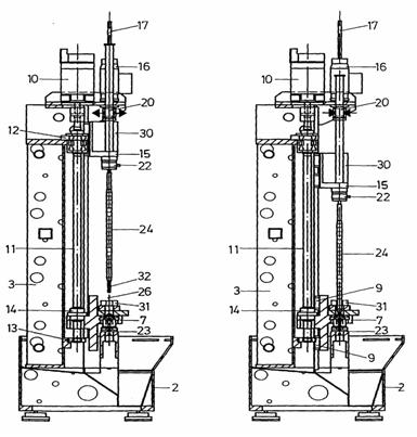
This place covers:
Machines specifically designed for reaming. Reaming involves enlarging the size of a previously formed hole by a small amount but with a high degree of accuracy to leave smooth sides through the removal of chips using a tool rotating relatively to a workpiece about the axis of the hole to be produced and moving along this axis relatively to the workpiece. It is to be noted that most reaming is carried out on machines also designed for drilling and tapping, which machines are not classed in B23D 75/00, as they are not specifically designed for reaming.
A reaming tool usually includes a short inclined major cutting edge and a longer calibrating auxiliary edge. A reaming tool is also used such that its axis is generally coincident with the axis of the bore being reamed and the feed movement is generally along this axis. Some fine boring heads (B23B 29/03, B23B 29/034) also exhibit these properties. Conversely milling tools (B23C 5/00) generally have longer major cutting edges, shorter auxiliary cutting edges and the feed motion between tool and workpiece is transverse to the axis of rotation of the tool, except in plunge milling.
Many of the adjustment mechanisms for cutting inserts within a milling tool (B23C 5/24) would also be applicable to reaming tools.
This place does not cover:
Boring heads | |
Chucks suitable for reaming and other tools | |
Milling tools | |
Honing devices or tools | |
Handles for hand implements |
Attention is drawn to the following places, which may be of interest for search:
Adjustment of cutting insert in turning tool holder | |
Boring heads with tools adjustable radially before commencing machining | |
Chucks for holding tools | |
Drilling tools | |
Drilling tools with provision for cooling | |
Milling cutters with shafts | |
Milling cutters having adjustable bits or teeth | |
Milling cutters with provision for cooling | |
Constructional details of machine tools in general not particularly related to the operation being performed | |
Provision of cooling within machine tools |
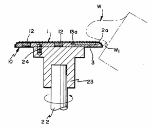
This place covers:
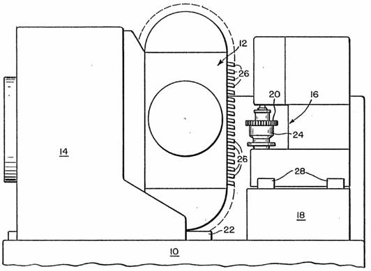
Reaming tools. Reaming involves enlarging the size of a previously formed hole by a small amount but with a high degree of accuracy to leave smooth sides through the removal of chips using a tool rotating relatively to a workpiece about the axis of the hole to be produced and moving along this axis relatively to the workpiece. A reaming tool usually (but not necessarily) includes a short inclined primary cutting edge and a longer calibrating auxiliary edge.
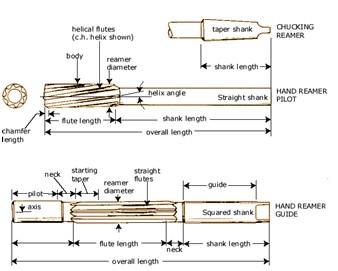
Reamer. Nomenclature of reamer shown B23D 77/00
Reamer with unequal distribution of flutes to prevent chatter (vibration) B23D 77/003
securing arrangement for insert in reamer B23D 77/025
Adjustment of diameter by oblique planes (15,22) B23D 77/042
Adjustment of diameter by screws B23D 77/044
adjustment of diameter by radial cams B23D 77/046
Adjustment of diameter by conical screws B23D 77/048
Expandable reamer with slots B23D 77/08
Expandable reamer without slots B23D 77/10
Tapered reamer B23D 77/12
A reaming tool usually includes a short inclined major cutting edge and a longer calibrating auxiliary edge. A reaming tool is also used such that its axis is generally coincident with the axis of the bore being reamed and the feed movement is generally along this axis. Some fine boring heads (B23B 29/03, B23B 29/034) also exhibit these properties though usually boring heads do not have a calibrating auxiliary cutting edge. Conversely milling tools (B23C 5/00) generally have longer major cutting edges, shorter auxiliary cutting edges and the feed motion between tool and workpiece is transverse to the axis of rotation of the tool, except in plunge milling.
Many of the adjustment mechanisms for cutting inserts within a milling tool (B23C 5/24) would also be applicable to reaming tools.
Attention is drawn to the following places, which may be of interest for search:
Adjustment of cutting insert in turning tool holder | |
Boring heads | |
Boring heads with tools adjustable radially before commencing machining | |
Chucks suitable for reaming and other tools | |
Chucks for holding tools | |
Drilling tools | |
Drilling tools with provision for cooling | |
Milling tools | |
Milling cutters with shafts | |
Milling cutters having adjustable bits or teeth | |
Milling cutters with provision for cooling | |
Constructional details of machine tools in general not particularly related to the operation being performed | |
Provision of cooling within machine tools | |
Honing devices or tools | |
Handles for hand implements |
For B23D 77/00 and subgroups, a 2000-series Indexing Code system is present (B23D 2277/00). Indexing Codes this series should be allocated at every opportunity. When classifying reaming tools particular attention should be paid to the Indexing Codes. Indexing Codes should also be added routinely to give details of the workpiece or tool configuration.
For example, a document showing a particular reaming tool having a particular configuration of adjustment mechanism for the cutting blade and showing explicit provision for coolant may be given a classification for the details of the adjustment mechanism as this forms the subject of the invention. Such a document should also be allocated Indexing Codes relating to the provision of coolant and/or further details of the reaming tool itself to allow easy retrieval.
The 2000-series Indexing Codes relating to the material of tool or workpiece should also be routinely allocated where available. However, in this instance, where a material is generally used for a particular part (e.g. tungsten carbide for an cutting insert or blade, steel for a reaming cutter body), the Indexing Code for the material concerned should only be allocated if further details of the material itself are present in the document.
This place covers:
Methods, machines, or devices not covered elsewhere, for working metal by removal of material.
Illustrative example of subject matter classified in this group:
Thermal deburring of workpiece (2) in a chamber (14) by igniting a mixture of gas (from supply 19) and oxygen (from supply 23) using a spark providing device (16). This type of device is commonly used to deburr inaccessible intersections of drilling within workpieces. B23D 79/005
Scraping (deburring) device to remove dross from end of cut metal workpiece B23D 79/02
Hand scraping device for deburring and/or cleaning B23D 79/02
Removal of internal bead from pipe by scraping B23D 79/023
Removal of internal pipe bead with additional equipment (hot gas31) B23D 79/025
Scraping device with rotating cutting tool B23D 79/04
Scraping devices with reciprocating tool B23D 79/06
Hand scraping device for deburring B23D 79/08
Bar peeling device not working by turning B23D 79/12
This group is only used when the removal of metal cannot be classified in a more suitable field elsewhere in the CPC schemes.
Attention is also drawn to the notes for B23, which define the term "metal" as including other materials unless the context determines otherwise. In this group the inclusion of the word "metal" indicates that this group should not be used for the removal of materials other than metal.
This place does not cover:
Removal of material by combined operations all classed within B23D | |
Cutting (including deburring) by electro-erosion (EDM) or electro-chemical machining (ECM) | |
Cutting (including deburring) by electron-beam | |
Cutting (including deburring) by laser beam | |
Work holding devices for machine tools | |
Handles suitable for hand scraping implements |
Attention is drawn to the following places, which may be of interest for search:
Removal of material by planing (shaping), slotting, shearing, broaching, sawing, filing, rasping or reaming: Like operations for working metal by removing material, not otherwise provided for | |
Cleaning using scrapers | |
Removal of material by turning, boring, drilling; in particular: | |
Machines or devices for chamfering the ends of bars or tubes | |
Chucks suitable to hold scraping and other tools | |
Deburring by use of a drilling tool | |
Removal of material by milling; in particular: | |
Deburring by milling | |
Cutting (including deburring) by electro-erosion (EDM) or electro-chemical machining (ECM) | |
Cutting using flames (e.g. oxy-acetylene) | |
Cutting (including deburring) using an arc | |
Cutting (including deburring) using Plasma | |
Cutting (including deburring) by electron-beam; Auxiliary devices for flash removal after welding | |
Removal of material by combined operations not all classed within B23D | |
Removal of material by grinding; in particular: Deburring or cleaning by grinding | |
Cutting using liquid jets containing abrasive; Deburring using liquid jets using liquid without abrasive particles | |
Work holding devices for machine tools | |
Severing using a liquid jet, not containing abrasive particles |
Classification B23D 79/00 is according to the literal interpretation of the subgroup headings, taking into account the notes concerning precedence rules and the references contained within the subgroups.
This place covers:
Methods, machines, or devices for working metal, covered by more than one main group in B23D 1/00 - B23D 79/12.
This place does not cover:
Making metal objects by operations essentially involving machining but not covered by a single other subclass | |
Making specific metal objects by operations not covered by a single other subclass | |
Machines or arrangements of machines for performing specified combinations of different metal-working operations not covered by a single other subclass |